Geometry Tool - Insert a Located
User Beam
(Revised: 04/01/08)
This
option is used to insert a located user beam in the building so that fit up is
ensured. The best use of this command is for complex geometry conditions and not
simple framing conditions. Any two points will define the top of the FO for a
located user beam. The orientation of the web will be vertical.
From the toolbar select the “Geometry Tools”
(hammer icon) ![]()
|
|
1.
Define the first point on the first frame using the Line
to Line intersection described in step 1. 2.
Define the second point on the other frame using the Line
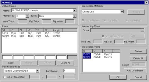
to Line intersection described in step 1 3.
There should be two intersection points in the Intersection Points list. Select both points by
holding down the control key. The points should highlight in yellow and an
orange line will extend between the points. 4.
Note: Check that the “Z” coordinates are the same to assure
that the new beam will run horizontally. 5.
Select the “Add User Beam” button. |
|
|
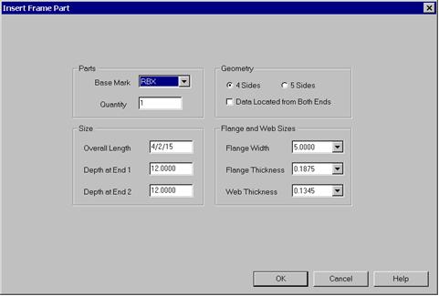
6.
Fill in the information for the user beam in the dialog
box. 7.
Select OK 8.
The located user beam is added in the tree under User Frame
Parts and can be treated just like any other frame member to modify. Note
that the new beam will not appear on screen until you OK out of the Geometry
Tool and Refresh the Tree, or until you select it as an active frame as
directed below. 9.
After the initial creation of the user beam, flange cuts
can be added. |
|
|
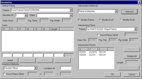
10. Select the new User Frame Part from the Active Frame list. 11. Select the Member
ID. 12. Select the
orientation view command and select “F” and then apply. This will give
a top view. 13.
Select the “Plane to Member” in the Intersection Methods box. 14. Select the Modify
Frame check box. 15. Select Modify
End 1. Note: The green dot indicates End 1 (see graphics screen) 16. Select the Frame that End 1 of the user beam
will be attached to, at the Intersecting Plane box. 17. In most cases you
will need to use an “Out of Plane Offset” of half of the web
thickness. 18. Select the “Intersect”
button and the intersection points should be shown in the Intersection Points list and the
member should be modified. 19. Repeat for the
other end of the user beam. Remember to change the Intersecting Plane and the
Modify End 2 button. 20. The Hip frame can
then be cut back using “Add FO Bracket – Break Flat Under Flange”. |